

In the complex landscape of modern automotive electronics, the Controller Area Network (CAN) bus system plays a pivotal role in enabling seamless communication between various components. However, troubleshooting issues within this intricate network can often pose challenges.

This is where the multimeter emerges as an invaluable tool, providing enthusiasts and mechanics alike with the means to test CAN bus wiring effectively. The CAN bus, responsible for transmitting data between electronic modules, requires proper wiring for seamless operation.
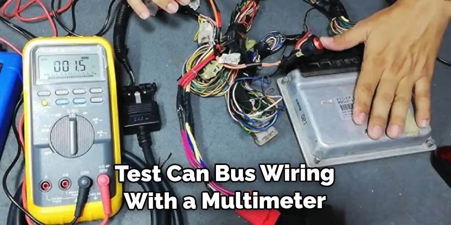
Faulty connections, breaks, or shorts in the wiring can lead to communication breakdowns and system malfunctions. In this article, we delve into the fundamental steps and techniques involved in how to test can bus wiring with multimeter.
From understanding the basics of CAN bus operation to grasping the nuances of multimeter utilization, readers will gain insights into diagnosing wiring problems swiftly and accurately. Whether you’re a seasoned automotive technician or an eager DIYer, mastering this skill empowers you to unravel the mysteries hidden within the wires and restore the optimal functionality of your vehicle’s electronic systems.
Importance of Proper Wiring and Communication for CAN Bus Systems
When it comes to vehicles, CAN bus systems are critical for the efficient operation of a vehicle. CAN stands for Controller Area Networking; these are the networks that control virtually all electronic functions within the car. Without proper wiring and communication on the CAN bus system, your vehicle can experience a wide range of issues, from major faults to minor ones.
It is important to properly test CAN bus wiring with a multimeter to ensure that it is up to specifications. Testing the wiring will allow you to identify any problems with the wiring or communication and take prompt action before they cause any further damage.
Testing for short opens, or high resistance values on multiple CAN lines requires careful analysis of the system. Using a multimeter can help you identify any shorts, opens, or high resistances that could be causing communication issues on the CAN bus. If these problems are identified early, it can save you time and money in the long run.
To begin testing the wiring with a multimeter, make sure all power is disconnected from the system before beginning. Next, check for continuity between each CAN line to ensure that the wiring is not open.
This will help you identify any breaks in the wiring or poor connections. Finally, check for shorts by measuring the resistance between each wire. If there is an abnormally low resistance value, it’s likely that there is a shortage on one of the CAN lines.
Purpose of Testing CAN Bus Wiring with a Multimeter
Testing CAN bus wiring with a multimeter is an essential part of maintaining a reliable and secure CAN bus network. A multimeter, or digital voltmeter, is used to measure the voltage (in volts), current (in amps), and resistance (in ohms) of an electrical circuit. With these measurements, you can diagnose problems with the wiring, such as shorts, open circuits, reversed connections, and more.
Using a multimeter to test CAN bus wiring is a simple process which requires few additional tools or materials. To begin the testing process, first, turn off the device that the CAN bus is connected to so that electricity does not flow through it.
Then, set your multimeter to measure for continuity and connect one of its leads to one of the wires in the CAN bus. Connect the other lead to another wire in the CAN bus, and make sure you have a good connection by gently wiggling them if necessary. If there is continuity between two wires, then it means that they are properly connected, and no further testing is required.
If there is no continuity between two wires, then you need to make sure that there is no fault in the CAN bus wiring. To do this, you can use a continuity tester or an ohmmeter which will measure the resistance across the wires and identify any potential problems in the wiring. If all readings come back to normal, then it is likely that a component in the device connected to the CAN bus is causing the issue and should be replaced.

10 Steps How to Test Can Bus Wiring with Multimeter
Step 1: Grasp the Fundamentals of the CAN Bus System
Begin by building a solid foundation of knowledge about the CAN bus system. Understand its architecture, communication protocols (CAN 2.0A and CAN 2.0B), message formats, and error-handling mechanisms. This understanding will help you grasp the significance of each step in the testing process.
Step 2: Assemble Necessary Tools and Resources
Collect all the essential tools and resources required for this task. Obtain a digital multimeter equipped with functions such as resistance, continuity, and voltage measurement. Additionally, acquire a comprehensive wiring diagram specific to your vehicle’s make and model. This diagram will be your roadmap to identifying CAN bus wiring routes and connections.
Step 3: Prioritize Safety Measures
Working with automotive electrical systems demands meticulous safety precautions. Begin by disconnecting the vehicle’s battery to eliminate the risk of electrical accidents. Equip yourself with appropriate safety gear, including insulated gloves, safety glasses, and protective clothing, before proceeding with the testing.
Step 4: Locate the CAN Bus Wiring
Consult the wiring diagram to identify the path of the CAN bus wiring throughout the vehicle. Generally, the wiring traverses the length of the vehicle, connecting various electronic modules and components. Take your time to locate connectors, access points, and junctions where testing will be conducted.
Step 5: Visual Inspection for Physical Damage
Before applying any measurements, visually inspect the CAN bus wiring for signs of physical damage. Look for cuts, abrasions, exposed wires, or any visible anomalies. Address these issues before proceeding with testing to ensure accurate results.
Step 6: Test for Continuity and Open Circuits
Set your multimeter to the continuity or resistance mode. Attach one probe to each end of the CAN bus wire you intend to test. A reading close to zero indicates continuity, indicating that the wire is intact. However, if the multimeter reads infinite resistance, it suggests an open circuit—a break in the wire that needs further investigation.
Step 7: Measure Resistance
In cases where continuity testing reveals an issue, proceed to measure the resistance of the CAN bus wiring. Compare the measured resistance with the manufacturer’s specifications. A significant deviation from the expected value could point to problems such as shorts, high resistance, or impedance mismatches within the wire.
Step 8: Voltage Measurement for Power Supply
To verify the adequacy of the voltage supply, set the multimeter to the voltage measurement mode. Connect the multimeter probes to the CAN bus power and ground terminals. The voltage reading should align with the manufacturer’s specified range. Any deviations from this range might indicate irregular power supply issues that can disrupt the communication network.

Step 9: Thoroughly Inspect Connectors and Termination Points
Examine the connectors and termination points along the CAN bus wiring. Ensure they are clean, properly seated, and free from corrosion. Loose or corroded connectors can introduce resistance or signal disruptions, affecting the network’s performance.
Step 10: Advanced Network Analysis Using an Oscilloscope
For advanced troubleshooting and analysis, consider utilizing an oscilloscope to study the CAN bus network’s waveform. This approach provides insights into signal quality, timing, and potential anomalies that may not be evident through basic multimeter measurements. An oscilloscope can help diagnose issues such as reflections, noise, and signal integrity problems within the network.
Safety Precautions When Testing Can Bus Wiring with Multimeter
It is important to take precautionary measures when testing Can Bus wiring with a multimeter. Before beginning, make sure the power supply to the circuit is turned off. It is also recommended that the test be done in an area away from flammable materials and sparks can occur. Ensure that all people present in the area have been briefed on safety procedures before testing begins.
When using the multimeter, it is important to set it to the correct setting in order for readings to be accurate. A low-ohm setting should be chosen when testing Can Bus wiring as this will give the most precise readings. Additionally, make sure that the probes of the meter are secure and touching only one wire at a time. A reading of 0 ohms should be taken from each wire to the ground in order to ensure that the wiring is properly isolated.

It is also important to check the wires for any signs of wear and tear, such as corrosion or fraying. This can affect the wiring’s ability to carry signals and should be replaced immediately if detected. In addition, make sure that all connections are secure and free of any debris. Any loose, damaged, or otherwise compromised wires should be replaced to ensure that the system is functioning properly.
Conclusion
Testing your CAN bus wiring with a multimeter is a simple but important task that should be part of your regular maintenance routine. You can troubleshoot any power supply, grounds, and shorts quickly by identifying their source using the multimeter.
Doing it yourself can save you time and money compared to expensive repair or replacement costs. Best of all, the steps detailed here are easy enough for anyone to do without the assistance of an experienced technician.
By following these steps, you will be able to test your CAN bus wiring in no time at all and spot issues before they become more serious. So, now that you know how to test can bus wiring with multimeter, why not give it a try? You might just surprise yourself with what skills you have already obtained!
