
How to test transmission control module with multimeter is an essential procedure for ensuring the effective operation of a vehicle’s transmission system.
The TCM is a critical electronic component that manages the transmission’s functions, such as shifting gears at the proper time and regulating hydraulic pressure. When issues arise like erratic shifting, slipping gears, or transmission warning lights, it may be necessary to test the TCM to diagnose potential faults. Using a multimeter, automotive technicians and enthusiasts alike can measure voltage levels and resistance in the TCM circuits, helping to identify whether the TCM itself is faulty or if the issue lies elsewhere in the transmission system.

This guide will provide you with the steps necessary to conduct this test safely and accurately, ensuring the reliable performance of your vehicle’s transmission.
What Will You Need?
- Multimeter (with voltage and resistance measurement capabilities)
- Safety gear (gloves, goggles, etc.)
- Vehicle owner’s manual or wiring diagram for the TCM
Once you have gathered the necessary materials, you can test the TCM.
9 Easy Steps on How to Test Transmission Control Module With Multimeter
Step 1: Prepare Your Vehicle
Ensure your vehicle is parked on a level surface and the engine is turned off. For added safety, engage the parking brake to prevent any accidental car movement during the testing process. Open the hood to access the vehicle’s battery and disconnect the negative cable. This is a crucial safety step, as it helps to prevent electrical shorts and ensures that you do not accidentally activate any electronic components while performing the test.
Next, consult the vehicle’s owner’s manual or TCM wiring diagram to confirm the location of the TCM within the vehicle. The TCM may be situated near the engine compartment, beneath the dashboard, or even adjacent to the transmission itself, depending on the make and model of your vehicle. Identifying its exact location will aid in a streamlined testing process. Once you’ve located the TCM, prepare for the next step, which is to use the multimeter to check the TCM circuits.
Step 2: Set Up the Multimeter

Before testing the circuits, set your multimeter to the appropriate settings based on your vehicle’s specifications. Generally, you’ll want to switch the multimeter to measure DC voltage and resistance (ohms). Referring to the vehicle owner’s manual or wiring diagram is important to know the correct parameters expected from a functioning TCM. Once you’ve set up your multimeter correctly, you’re ready to measure the voltage levels and resistance within the TCM circuits, ensuring your readings fall within the specified range as outlined by your vehicle’s technical documentation. Accurate setup of the multimeter is vital to obtaining valid readings and preventing potential damage to the multimeter or vehicle electronics.
Step 3: Measure the Voltage at the Power Supply Terminal
With the multimeter configured, the next step involves measuring the voltage at the TCM’s power supply terminal. Reconnect the negative battery cable to power the system. Locate the power supply terminal on the TCM using the wiring diagram, which should indicate the expected voltage range. Place the multimeter’s positive probe on the TCM power supply terminal and the negative probe on a suitable ground. Record the voltage reading displayed on the multimeter.
The voltage should match the expected reading as per the vehicle’s documentation. If the voltage is outside this range, there may be a problem with the power supply or wiring to the TCM, and further investigation may be necessary to identify the source of this discrepancy before proceeding with additional tests.

Step 4: Check Ground Connections
After verifying the voltage at the power supply terminal, the next step is to ensure that the TCM is adequately grounded. A solid ground connection is essential for the TCM to function correctly. Using the vehicle’s wiring diagram, identify the ground terminal on the TCM. Set your multimeter to measure resistance (ohms).
Disconnect the negative probe from the ground used in the previous step and connect it to the TCM’s ground terminal. Place the positive probe on a known good ground point on the vehicle’s chassis. The multimeter should read close to zero resistance, indicating a proper ground connection. If the resistance is significantly higher, this may suggest a bad ground connection, which can cause erratic TCM behavior. In such a case, inspect the ground strap or wire for corrosion or damage and address any issues found.
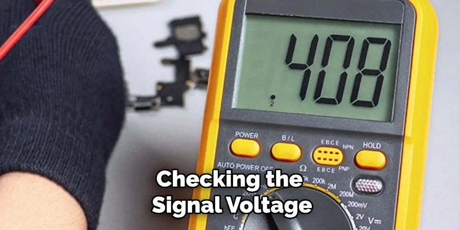
Step 5: Inspect Signal Voltage
The next part of the TCM testing process involves checking the signal voltage. Signal voltage is a crucial component for the TCM as it receives commands and data from various sensors around the vehicle. To perform this test, refer to the wiring diagram to locate the signal input terminal on the TCM. Set your multimeter to measure DC voltage. Turn the ignition to the “ON” position without starting the engine to activate the vehicle’s electronics. Use the positive probe to touch the TCM’s signal input terminal and the negative probe to connect to a proper ground. Observe the reading displayed on the multimeter. The voltage should be within the range specified by the vehicle’s technical manual.
Step 6: Test the Resistance of the Solenoid
Solenoids play a vital role in controlling the flow of hydraulic fluid within the transmission, and a malfunctioning solenoid can lead to erratic transmission behavior. First, To test the solenoid circuits’ resistance, locate the solenoid terminals on the TCM using the wiring diagram for reference. Set your multimeter to measure resistance (ohms) and ensure the ignition is turned off before proceeding. Connect the multimeter probes to the solenoid terminals, ensuring proper contact.
The resistance should match the specifications provided in the vehicle’s manual. A reading outside of this range may indicate a faulty solenoid or issues within the wiring. Addressing any inconsistencies here is essential since the solenoids ensure the smooth operation of the transmission system by controlling fluid flow based on TCM instructions.
Step 7: Evaluate the TCM Temperature Sensor
The temperature sensor within the TCM monitors the transmission fluid’s temperature, which is crucial for maintaining optimal transmission performance and longevity. To assess the temperature sensor’s functionality, refer to the vehicle’s wiring diagram and locate the temperature sensor terminal on the TCM. Configure your multimeter to measure resistance (ohms) and ensure the ignition is off.
Connect the multimeter probes to the temperature sensor’s terminals. Start by reading at ambient temperature and recording the resistance. You should slowly warm the transmission fluid by starting the engine and allowing the vehicle to idle. Monitor the resistance as the fluid increases in temperature; the resistance should change according to the specifications outlined in the vehicle’s manual. Anomalies in resistance changes can indicate a faulty temperature sensor, leading to inadequate adjustments in transmission performance.
Step 8: Verify CAN Bus Communication
The Controller Area Network (CAN) bus is integral to modern vehicle networks and facilitates communication between the TCM and other electronic control units (ECUs). Verifying that the CAN bus communication is functioning correctly is crucial in ensuring the TCM is operating properly. To check the CAN bus, use a scan tool compatible with your vehicle’s make and model. Connect the scan tool to the vehicle’s diagnostic port, usually under the dashboard. Power on the scan tool and select the option to read CAN bus codes.

A healthy CAN bus should not display any error codes related to communication faults. If error codes are present, they may indicate a break in the communication lines, faulty wiring, or an issue with one of the connected ECUs. Investigating and addressing these issues will help maintain the smooth data exchange necessary for optimal transmission control.
Step 9: Reassemble and Road Test
Once all tests have been completed and any issues addressed, it’s time to reassemble any removed components during the testing process. Ensure that all connectors and wiring harnesses are securely reattached and that any panels or covers are replaced. After reassembly, perform a road test to ensure that the transmission system is operating smoothly and that the TCM is providing the correct signals to the transmission. Pay attention to gear shifting smoothness, response times, and any unusual noises or vibrations that could indicate unresolved issues. If the transmission behaves as expected, this confirms that the TCM and associated components are functioning correctly.
By following these steps and carefully conducting TCM testing, automotive technicians can accurately diagnose and address any issues within the transmission control system.
Conclusion
How to test transmission control module with multimeter requires careful attention to detail and a systematic approach.
By following the outlined steps, technicians can effectively diagnose and resolve potential issues within the system. Initial checks involve verifying signal input voltage and solenoid resistance, along with assessing the TCM temperature sensor and CAN bus communication. Each test is critical in ensuring the TCM commands are accurately executed, leading to optimal transmission performance. Completing these procedures helps identify faulty components or wiring issues and prevents future transmission failures.
Comprehensive road testing and final diagnostics further solidify the TCM’s integrity, confirming that the module is operating as expected. This systematic approach ensures the reliability and longevity of the vehicle’s transmission system.
Occupation: Expert in Hardware Tools
Education: Bachelor’s Degree in Mechanical Engineering
Profile:
Enrique Howard is a seasoned expert in the field of hardware tools, with a robust background in mechanical engineering that underpins his extensive knowledge and skills. Holding a degree in mechanical engineering, Enrique has cultivated a deep understanding of tool design, mechanics, and the intricacies of various hardware applications. His educational foundation empowers him to innovate and refine tools that enhance efficiency and effectiveness in a wide range of industries.
Professional Focus:
Enrique’s professional focus encompasses a diverse array of areas within the hardware tools sector, including:
- Tool Design and Development: Leveraging his engineering expertise, Enrique specializes in designing tools that meet specific user needs, ensuring optimal performance and durability.
- Material Science: Understanding the properties of various materials allows him to recommend the best tools for specific applications, enhancing safety and efficiency.
- Ergonomics: He emphasizes the importance of ergonomic design in tools, striving to create solutions that reduce user fatigue and improve comfort during prolonged use.
- Sustainability: Enrique is committed to promoting environmentally friendly practices in tool manufacturing, advocating for the use of sustainable materials and processes.
- Education and Training: Through workshops, seminars, and written content, he focuses on educating both professionals and DIY enthusiasts about tool selection, maintenance, and safe usage practices.
Throughout his career, Enrique has worked on numerous projects, collaborating with manufacturers and craftsmen to develop cutting-edge hardware solutions. His expertise spans from traditional hand tools to advanced power tools, allowing him to contribute significantly to both professional and DIY communities.
As an author, Enrique shares his insights through articles, guides, and tutorials, aimed at helping enthusiasts and professionals alike navigate the complexities of hardware tools. His passion for education and practical application drives him to continually explore new technologies and methodologies, making him a trusted voice in the hardware industry.
Whether he’s writing about the latest tool advancements or providing practical tips for tool maintenance, Enrique Howard is dedicated to empowering others with the knowledge and skills necessary to excel in their hardware endeavors.