
How do you test cable signals with a multimeter? Look no further, as we have got you covered.
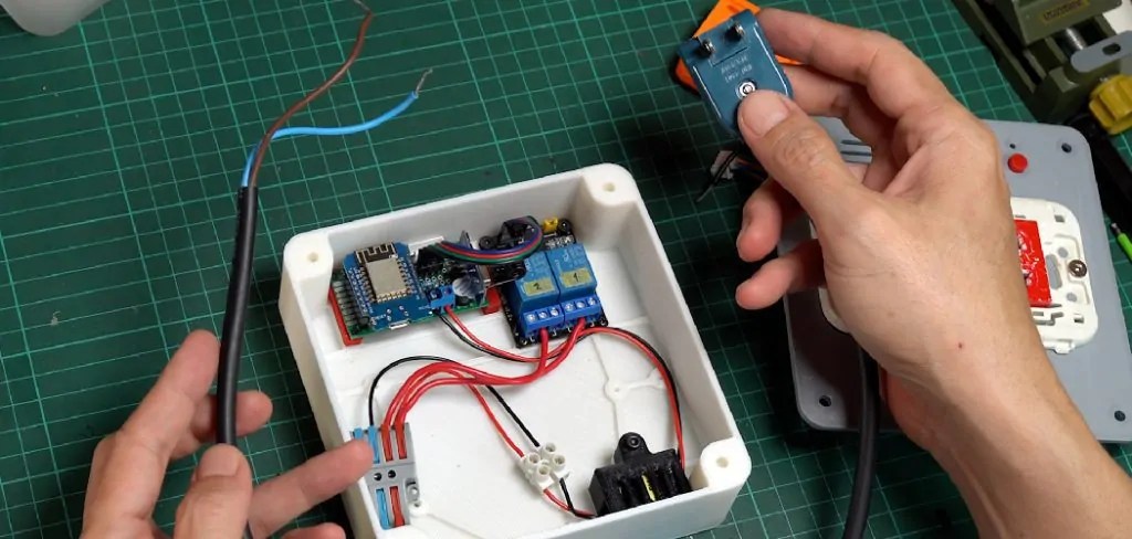
Testing a cable signal with a multimeter is a practical way to diagnose and troubleshoot common issues in your cable connections. Whether dealing with audio, video, or data cables, verifying the signal integrity ensures optimal performance of your electronic devices. A multimeter, a versatile diagnostic tool, allows you to measure voltage, current, and resistance, helping you pinpoint any disruptions or losses in the cable signal. As a result, you can identify the defective component and take necessary steps for repairs or replacements.
This guide will walk you through the essential steps of how to test cable signal with multimeter, ensuring that you can efficiently maintain and optimize your cable connections.
What Will You Need?
Before we dive into the testing process, let’s ensure you have all the necessary tools and materials. Here is a list of items that you will need to test your cable signal with a multimeter successfully:
- A Multimeter: preferably one with multiple features such as voltage, current, and resistance measurement capabilities.
- Test Leads or Probes: these are essential for making accurate measurements using the multimeter.
- Cable to be tested: ensure the cable is in good condition and free from any visible damages.
- Safety Glasses: Protecting your eyes when dealing with electrical equipment is always a good idea.
- A Reference Cable: this can be a known working cable of the same type as the one you are testing. It will help provide a baseline for comparison during the testing process.
Once you have gathered all the necessary tools and materials, you can begin the testing process.
10 Easy Steps on How to Test Cable Signal With Multimeter
Step 1. Safety First:
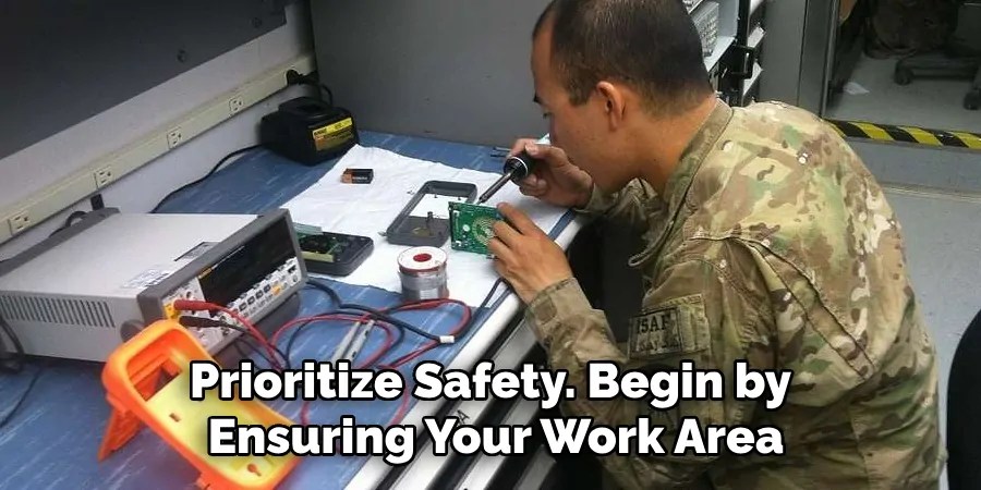
Before starting any testing procedure with electrical components, prioritize safety. Begin by ensuring your work area is clean and free from potential hazards. Remove any liquids or flammable materials nearby, as these can pose risks when working with electrical devices. Wear your safety glasses to protect your eyes from accidental sparks or debris. Additionally, make sure your hands are dry and, if necessary, wear insulating gloves to prevent electrical shocks.
Familiarize yourself with the multimeter’s functions and safety settings, ensuring it is turned off before connecting it to any cable. Always handle the test leads carefully, ensuring they do not cross or touch inappropriately, which can lead to short circuits. Lastly, verify that the power to the system or device to which the cable is connected is turned off to avoid any unexpected electric current flow during the testing process. Prioritizing these safety measures ensures a smooth and secure testing experience.
Step 2. Set Up Your Multimeter:
Begin by selecting the appropriate setting on your multimeter for the type of measurement you plan to make. If you’re checking for continuity, set the multimeter to the continuity test mode, often represented by a diode symbol or sound wave icon. Set it to AC or DC voltage for voltage testing based on the cable’s power source. If measuring resistance, switch to the ohm setting.
Once the correct setting is chosen, connect the test leads to the multimeter: insert the red lead into the corresponding positive terminal and the black lead into the joint (COM) terminal. Double-check these connections to ensure accuracy and safety. Before testing, confirm that your multimeter is functioning correctly by testing it with a known working cable or using the reference cable to establish a baseline.
Step 3. Inspect the Cable Visually:

Before using the multimeter, thoroughly inspect the cable to identify any obvious signs of damage. Look for cuts, frays, or cracks on the cable’s outer jacket, as these can compromise the signal quality. Examine the connectors on both ends for corrosion, bent pins, or loose connections. Damaged connectors or exposed wires can lead to signal loss or interference. A visual inspection highlights visible problems that can be resolved before testing and helps ensure that any discovered issues won’t cause inaccurate multimeter readings. If you identify any significant physical damage, consider replacing or repairing the cable before proceeding with further testing.
Step 4. Test for Continuity:
Perform a continuity test to ensure that your cable is conducting electricity properly. Set your multimeter to the continuity setting, which may emit a beep sound when the circuit is complete. Place one probe on one end of the cable and the other probe on the corresponding pin at the other end. If your multimeter beeps or shows a low resistance reading (close to zero), the cable has good continuity, meaning there are no broken wires inside. If there is no beep or the resistance is very high, it indicates an interruption in the cable, suggesting it might be damaged and need repair or replacement.
Step 5. Measure Resistance:
After testing for continuity, the next step is to measure the resistance of the cable. Set your multimeter to the ohm setting to measure resistance. Connect the multimeter probes to the two ends of the cable wires you want to test. Take note of the resistance reading displayed on the multimeter. A higher-than-expected resistance could indicate a problem, such as corrosion or a loose connection within the cable, which can impede the flow of electrical signals. Compare the resistance reading with the specifications provided by the cable manufacturer or a known working reference cable.
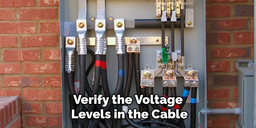
Step 6. Test for Voltage:
Once you have assessed both continuity and resistance, the next step is to verify the voltage levels in the cable. Set your multimeter to the appropriate AC or DC voltage setting, depending on the cable’s specifications. Carefully connect the test leads to the cable’s terminals or connectors—ensuring proper polarity with the red lead on the positive terminal and the black lead on the negative or ground terminal. Observe the multimeter display to check the voltage reading.
Compare it with the expected voltage range indicated by the cable or device manufacturer. A voltage reading within the specified range confirms that the cable can transmit electrical power effectively. If the voltage is too low or absent, inspect for possible issues such as faulty connections, defective cables, or malfunctioning power supply. During this test, always exercise caution to prevent electric shock or damage to the multimeter and other connected components.
Step 7. Test for Signal Loss or Attenuation:
The final step in evaluating cable integrity is to test for any signal loss or attenuation that may occur during transmission. This is particularly important for data or audio-visual cables. Connect the cable to a signal generator and a corresponding signal receiver or analyzer. Set the signal generator to emit a test signal at the frequency range applicable to the cable. Measure the strength of the incoming and outgoing signals with the signal analyzer.
Compare the results to determine if the signal has degraded beyond acceptable levels. Excessive attenuation may be due to poor shielding, degraded internal wires, or excessive cable length. If signal loss is detected, adjust the cable environment or replace the cable with one of a higher quality. Throughout this process, ensure all equipment is correctly calibrated, and the connections are secure to guarantee accurate readings.
Step 8. Document the Findings:
After completing all tests, it’s crucial to document the findings for future reference or analysis. Create a detailed record of each test, including results on continuity, resistance, voltage, and signal loss. Note any anomalies or deviations from expected values and the condition and type of cable tested.
Include dates and any corrective actions taken, such as repairs or cable replacements. Keeping an organized log helps track the performance and longevity of each cable and can be invaluable for troubleshooting potential issues in the future. This documentation can also assist in maintenance schedules and inventory management, ensuring optimal cable performance throughout its lifecycle.
Step 9. Evaluate the Environment:
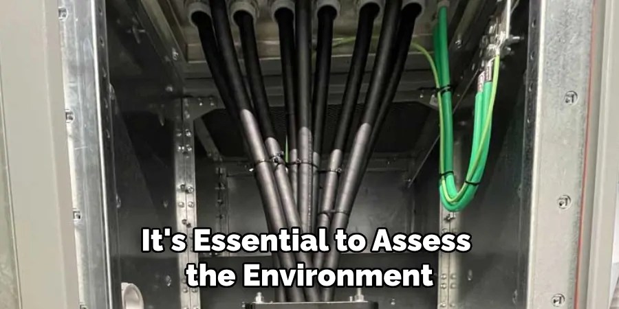
Beyond the technical aspects of the cable itself, it’s essential to assess the environment in which the cable operates. Environmental factors such as temperature, humidity, and electromagnetic interference can significantly impact cable performance. Inspect the cable’s routing to avoid exposure to extreme temperatures or physical stress from bending, stretching, or pinching. Look for potential sources of electromagnetic interference, such as motors, transformers, or wireless devices, which can affect signal transmission, especially in data cables.
Step 10. Implement Protective Measures:
Consider implementing protective measures to ensure the long-term reliability and performance of your cables. Use cable organizers or conduits to prevent tangling and protect against physical damage. Apply heat shrink tubing or braided sleeves to add extra protection, especially in high-stress areas. Use UV-resistant materials and weatherproofing techniques if cables are routed outdoors or in harsh environments.
By following these steps and implementing protective measures, you can ensure the integrity of your cables, prolong their lifespan, and prevent potential issues that could result in costly downtime or repairs.
Conclusion
In conclusion, how to test cable signal with multimeter involves a systematic approach to ensure the cables are functioning optimally and to identify any potential issues.
By following a defined process—starting with continuity tests, measuring resistance, verifying voltage levels, checking for signal loss or attenuation, and documenting findings—you can confidently assess the condition of the cables. Additionally, evaluating the operating environment and implementing protective measures further enhances cable reliability and longevity. This comprehensive examination not only aids in maintaining seamless operation but also helps prevent disruptions that could lead to costly repairs.
With careful attention and regular monitoring, your cables can continue to deliver effective performance over their lifespan.
Occupation: Expert in Hardware Tools
Education: Bachelor’s Degree in Mechanical Engineering
Profile:
Enrique Howard is a seasoned expert in the field of hardware tools, with a robust background in mechanical engineering that underpins his extensive knowledge and skills. Holding a degree in mechanical engineering, Enrique has cultivated a deep understanding of tool design, mechanics, and the intricacies of various hardware applications. His educational foundation empowers him to innovate and refine tools that enhance efficiency and effectiveness in a wide range of industries.
Professional Focus:
Enrique’s professional focus encompasses a diverse array of areas within the hardware tools sector, including:
- Tool Design and Development: Leveraging his engineering expertise, Enrique specializes in designing tools that meet specific user needs, ensuring optimal performance and durability.
- Material Science: Understanding the properties of various materials allows him to recommend the best tools for specific applications, enhancing safety and efficiency.
- Ergonomics: He emphasizes the importance of ergonomic design in tools, striving to create solutions that reduce user fatigue and improve comfort during prolonged use.
- Sustainability: Enrique is committed to promoting environmentally friendly practices in tool manufacturing, advocating for the use of sustainable materials and processes.
- Education and Training: Through workshops, seminars, and written content, he focuses on educating both professionals and DIY enthusiasts about tool selection, maintenance, and safe usage practices.
Throughout his career, Enrique has worked on numerous projects, collaborating with manufacturers and craftsmen to develop cutting-edge hardware solutions. His expertise spans from traditional hand tools to advanced power tools, allowing him to contribute significantly to both professional and DIY communities.
As an author, Enrique shares his insights through articles, guides, and tutorials, aimed at helping enthusiasts and professionals alike navigate the complexities of hardware tools. His passion for education and practical application drives him to continually explore new technologies and methodologies, making him a trusted voice in the hardware industry.
Whether he’s writing about the latest tool advancements or providing practical tips for tool maintenance, Enrique Howard is dedicated to empowering others with the knowledge and skills necessary to excel in their hardware endeavors.