
Testing an accelerator pedal sensor with a multimeter is essential for ensuring your vehicle’s throttle response remains efficient and reliable.

The accelerator pedal sensor, often called the throttle position sensor, is crucial in monitoring the pedal position and transmitting this information to the engine’s control unit. This process directly influences the engine’s performance. A faulty sensor can lead to various issues, including poor acceleration, engine stalling, or erratic idling. Using a multimeter, a handy diagnostic tool, you can efficiently test the sensor’s functionality, helping to identify any problems before they escalate into major repairs.
This introduction aims to guide you through the basic steps on how to test accelerator pedal sensor with multimeter.
What Will You Need?
- A multimeter
- Safety gloves and glasses
- Vehicle’s manual (for reference)
Ensure that the vehicle is parked on level ground, in a secure place, with the engine turned off before beginning the testing process. Additionally, safety gear should always be worn before working on any vehicle.
10 Easy Steps on How to Test Accelerator Pedal Sensor With Multimeter
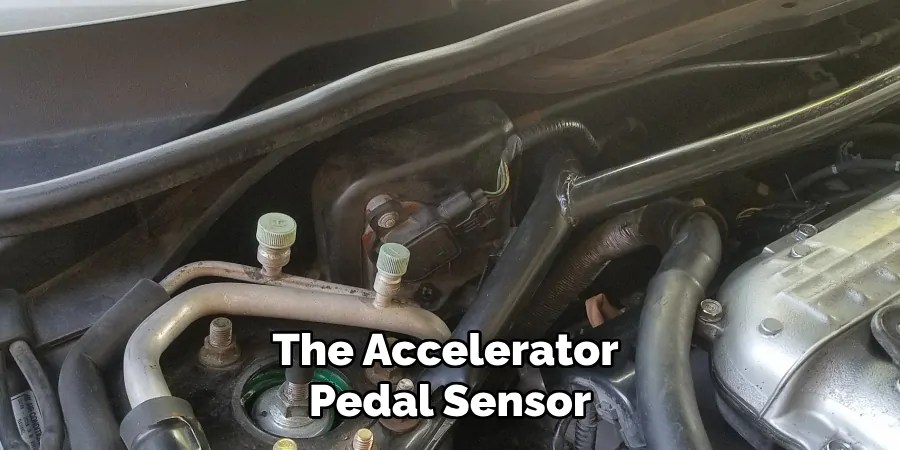
Step 1. Locate the Accelerator Pedal Sensor:
The accelerator pedal sensor is typically located near the pedal assembly within the driver’s side footwell area. To find the sensor, first, ensure you have your vehicle’s manual at hand, as this will provide specific details relevant to your vehicle model. Adjust the driver’s seat to gain better access to the pedal area. Once you’ve identified the general location, carefully inspect the area for the sensor, which is often part of a small module attached to the pedal assembly.
This module will generally have an electrical connector that links it to the vehicle’s electronic system. If you encounter difficulty finding the sensor, consult your vehicle’s manual for diagrams and possible location hints specific to your model. Proceed cautiously to avoid accidental damage to the wiring or surrounding components.
Step 2. Disconnect the Sensor’s Electrical Connector:
Before proceeding, ensure the vehicle’s engine is entirely off and the keys are removed from the ignition. Once you have located the accelerator pedal sensor, carefully disconnect the attached electrical connector. This connector is typically secured with clips or a locking mechanism, so gently press or lift the latch to release it without causing any damage to the wires or the connector itself.
Disconnecting the electrical connection ensures that no current passes through the sensor during testing, providing a safe environment for using the multimeter. If any resistance is encountered, refer to your vehicle’s manual for specific instructions on safely unlocking the connector mechanism.
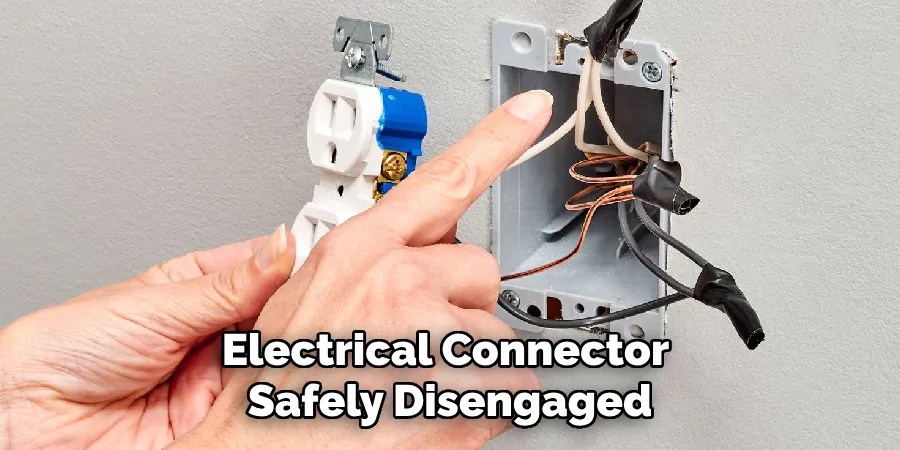
Step 3. Set the Multimeter to the Resistance Setting:
With the sensor’s electrical connector safely disengaged, it’s time to prepare your multimeter for testing. Set your multimeter to measure resistance, indicated by the device’s ohm symbol (Ω). If your multimeter has an auto-ranging feature, it will automatically select the appropriate range; otherwise, manually choose a range that includes the expected resistance value for the sensor.
Refer to your vehicle’s manual to obtain the resistance parameters associated with the accelerator pedal sensor, as these can vary by model and manufacturer. Ensuring correct multimeter settings is crucial for obtaining accurate and reliable test results during the diagnostic process.
Step 4. Measure the Sensor’s Resistance:
With the multimeter set to the correct resistance range, connect the multimeter’s probes to the appropriate terminals on the accelerator pedal sensor. Typically, these terminals are part of the sensor’s previously disconnected electrical connector. Carefully attach the multimeter’s positive (red) probe to one terminal and the negative (black) probe to the other.
It’s essential to refer to your vehicle’s manual or wiring diagram to ensure the correct terminals are being tested, as connecting the wrong ones may lead to inaccurate readings or damage the sensor. Once the probes are securely attached, observe the resistance reading displayed on the multimeter. Compare this value to the specified resistance range found in the vehicle’s manual. If the measured resistance falls outside the acceptable range, the sensor may be defective and require replacement.
Step 5. Check for Smooth Resistance Change
With the resistance measurement taken, it’s crucial to check for a smooth change in resistance as the accelerator pedal is pressed and released. While keeping the multimeter probes connected to the sensor terminals, slowly depress the accelerator pedal and observe the resistance reading on the multimeter. The resistance should change smoothly without any sudden jumps or drops, reflecting the gradual movement of the pedal.
A smooth, consistent change in resistance indicates that the sensor is functioning correctly. Conversely, if the resistance reading fluctuates erratically or displays sudden changes, this may imply a faulty sensor that requires replacement. Always perform this test multiple times to ensure consistency in the readings and verify the reliability of the sensor’s performance.
Step 6. Test Sensor’s Voltage Output
Once the resistance tests are complete, it’s essential to check the voltage output of the accelerator pedal sensor to confirm its overall functionality. Reconnect the sensor’s electrical connector securely, ensuring all latches and clips are properly engaged. Turn the vehicle’s ignition to the “on” position without starting the engine to supply power to the sensor. Then, reset your multimeter to measure voltage this time, ensuring it’s set to the appropriate voltage range.
Following the wiring diagram from your vehicle’s manual, locate the correct terminals on the back of the sensor’s connector for testing voltage output. Carefully attach the multimeter’s positive (red) probe to the voltage output terminal and the negative (black) probe to a good ground point on the vehicle. Slowly depress and release the accelerator pedal while observing the voltage reading: it should increase and decrease smoothly in correlation with the pedal movement.
A steady voltage change confirms that the sensor is operating correctly, while erratic voltage fluctuations may indicate a malfunction that necessitates repair or replacement.

Step 7. Reassemble and Test Drive the Vehicle
After confirming the sensor’s functionality through resistance and voltage testing, it’s time to reassemble the components and ensure everything is securely in place. Carefully remove the multimeter probes and reconnect any components or panels that were removed for access to the sensor. Double-check that all connections, clips, and screws are tight and secure to prevent any loose parts while driving.
Once reassembled, it’s advisable to test drive the vehicle in a safe area to observe the behavior of the accelerator pedal and ensure that the vehicle responds smoothly to acceleration inputs. This functional test will verify that the sensor is operating correctly and that the diagnostic and repair process was successful. If any issues persist, further investigation or professional assistance may be required.
Step 8. Seek Professional Assistance if Necessary
If you have completed the sensor testing and reassembly steps yet still encounter issues with the vehicle’s acceleration, it may be time to seek professional assistance. Persistent problems could indicate more complex underlying issues beyond the accelerator pedal sensor, such as wiring faults or ECU (Engine Control Unit) problems. A certified mechanic or automotive technician will have the expertise and diagnostic tools necessary to conduct a thorough investigation and pinpoint the exact cause of the problem.
Attempting to resolve complex issues without professional guidance may lead to further complications, so when in doubt, rely on expert advice to ensure your vehicle remains safe and functional.
Step 9. Regular Maintenance and Inspection
To maintain the optimal functionality of your vehicle’s accelerator pedal sensor and prevent future issues, incorporate regular maintenance and inspections into your routine. Periodically check the connections and wiring associated with the sensor to ensure they are secure and free from corrosion or damage. Clean the area around the accelerator pedal and sensor to prevent dirt and debris from affecting the sensor’s performance.

Additionally, adhere to your vehicle’s maintenance schedule as outlined in the owner’s manual, which may include periodic professional inspections of electronic components such as the accelerator pedal sensor.
Step 10. Document the Repair Process
After successfully diagnosing and resolving issues with the accelerator pedal sensor, it is beneficial to document the entire repair process. Keep a detailed record of the test results, any parts replaced, and the steps taken to fix the problem. This documentation can be a valuable reference for future troubleshooting and help track maintenance history. In addition, should you decide to sell your vehicle, having a well-documented repair and maintenance record can enhance its resale value by reassuring buyers about the vehicle’s condition.
By following these steps and incorporating regular maintenance, you can ensure your accelerator pedal sensor remains in good working condition and provides reliable and smooth acceleration for years to come.
Conclusion
In conclusion, how to test accelerator pedal sensor with multimeter involves a structured approach comprising several key steps.
Begin by ensuring a proper setup with access to the vehicle’s wiring diagram and preparing your multimeter for resistance and voltage measurement. Conduct initial resistance tests by observing smooth and consistent changes when the pedal is engaged, verifying the sensor’s responsiveness. Follow up with voltage output testing, ensuring a steady correlation between pedal movement and voltage readings. If anomalies are detected, further diagnostics or replacement of the sensor should be considered. After thoroughly testing and confirming the sensor’s functionality, reassemble all components securely and conduct a test drive to validate the repair.
These guidelines help ensure precise diagnostics and foster sustained peace of mind regarding your car’s acceleration functionality.
Occupation: Expert in Hardware Tools
Education: Bachelor’s Degree in Mechanical Engineering
Profile:
Enrique Howard is a seasoned expert in the field of hardware tools, with a robust background in mechanical engineering that underpins his extensive knowledge and skills. Holding a degree in mechanical engineering, Enrique has cultivated a deep understanding of tool design, mechanics, and the intricacies of various hardware applications. His educational foundation empowers him to innovate and refine tools that enhance efficiency and effectiveness in a wide range of industries.
Professional Focus:
Enrique’s professional focus encompasses a diverse array of areas within the hardware tools sector, including:
- Tool Design and Development: Leveraging his engineering expertise, Enrique specializes in designing tools that meet specific user needs, ensuring optimal performance and durability.
- Material Science: Understanding the properties of various materials allows him to recommend the best tools for specific applications, enhancing safety and efficiency.
- Ergonomics: He emphasizes the importance of ergonomic design in tools, striving to create solutions that reduce user fatigue and improve comfort during prolonged use.
- Sustainability: Enrique is committed to promoting environmentally friendly practices in tool manufacturing, advocating for the use of sustainable materials and processes.
- Education and Training: Through workshops, seminars, and written content, he focuses on educating both professionals and DIY enthusiasts about tool selection, maintenance, and safe usage practices.
Throughout his career, Enrique has worked on numerous projects, collaborating with manufacturers and craftsmen to develop cutting-edge hardware solutions. His expertise spans from traditional hand tools to advanced power tools, allowing him to contribute significantly to both professional and DIY communities.
As an author, Enrique shares his insights through articles, guides, and tutorials, aimed at helping enthusiasts and professionals alike navigate the complexities of hardware tools. His passion for education and practical application drives him to continually explore new technologies and methodologies, making him a trusted voice in the hardware industry.
Whether he’s writing about the latest tool advancements or providing practical tips for tool maintenance, Enrique Howard is dedicated to empowering others with the knowledge and skills necessary to excel in their hardware endeavors.