
Are you having trouble with a faulty 5-pin relay and want to test it yourself? Look no further, as this guide will walk you through the process of how to test a 5 pin relay with a multimeter.
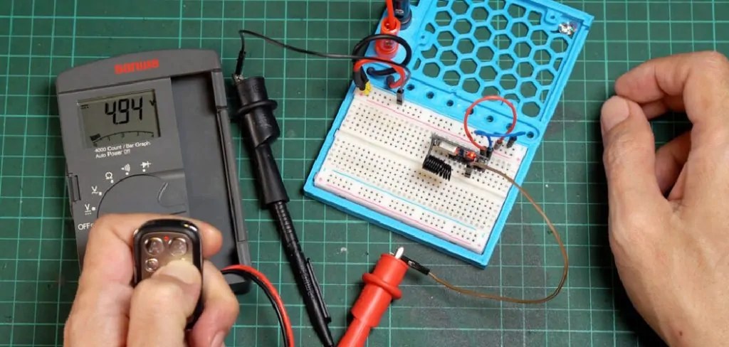
When diagnosing electrical issues in a vehicle or any electrical system, understanding how to test a 5-pin relay is crucial. A relay serves as a switch that opens and closes circuits, and it’s crucial to ensure it functions correctly. Using a multimeter, you can efficiently test the relay to determine if it’s faulty or in working condition. This process involves measuring resistance and continuity to assess the relay’s performance.
In the following sections, we will outline the steps to accurately test a 5-pin relay with a multimeter, ensuring reliable diagnostics and effective troubleshooting.
What Will You Need?
To test a 5-pin relay with a multimeter, you will need the following items:
- A digital multimeter
- The 5-pin relay in question
- A power source (such as a battery or power supply)
- Jumper wires
It’s important to use a digital multimeter for this process, as it provides more accurate readings compared to analog meters. Additionally, ensure that the battery or power supply has enough voltage to activate the relay.
10 Easy Steps on How to Test a 5 Pin Relay With a Multimeter
Step 1. Identify the Pins
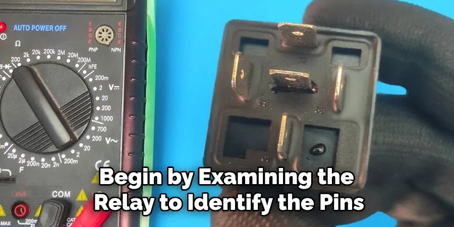
Begin by examining the relay to identify the pins, typically labeled on the relay casing or through a schematic diagram if available. A standard 5-pin relay will usually have the following pins: 85, 86, 87, 87a, and 30. Pins 85 and 86 are the coil terminals, which activate the relay when connected to an appropriate power source. Pin 30 is the common terminal, while pins 87 and 87a are the switched terminals. Pin 87 connects the current path when the relay is energized, whereas Pin 87a is connected when the relay is de-energized. Understanding the function of each pin will facilitate accurate testing, ensuring you can accurately assess whether the relay is functioning as intended.
Step 2. Test the Coil
Using your digital multimeter, set it to measure resistance (ohms). Connect the test leads to the coil terminals, pins 85 and 86. A functioning relay coil typically has a resistance reading within a specific range, usually between 50 and 200 ohms. If the resistance is significantly outside this range or shows as infinite, the coil may be open or shorted, indicating a faulty relay. This step is crucial in determining whether the electrically controlled switch is operational before proceeding to test further functionality.
Step 3. Test for Continuity of the Normally Closed Contact
Set your multimeter to the continuity setting. Place one test lead on pin 30 (the common terminal) and the other on pin 87a (the normally closed contact). Since pin 87a should be in contact with pin 30 when the relay is de-energized, the multimeter should beep, indicating continuity. If there is no continuity, it suggests the relay is defective or worn out. This test confirms the normal static position of the relay contacts before activating the coil for further testing.

Step 4. Test for Continuity of the Normally Open Contact
With the multimeter still set to the continuity setting, move one test lead from pin 87a to pin 87 (the normally open contact). Initially, there should be no continuity between pin 30 and pin 87 under inactive conditions, as the relay is not energized. Connect the power source to the coil terminals (pins 85 and 86) to energize the relay. When the relay is energized, pin 87 should connect to pin 30, completing the circuit. At this point, your multimeter should beep, indicating continuity between pins 30 and 87. If continuity is not present when the relay is activated, then the relay is likely faulty.
Step 5. Check for Coil Activation
Now, troubleshoot the relay by checking if the coil activates correctly with the power source. Reattach the power source to pins 85 and 86 to energize the relay. You should hear a distinct click, which signifies that the coil is operating and the relay is switching from its normally closed position to its normally open position. This audible confirmation indicates that the coil is engaging as expected. If you do not hear a click, it suggests a failure within the relay, preventing it from functioning correctly despite apparently average resistance and continuity readings.
Step 6. Verify the Coil’s Voltage Requirement
Before proceeding with further tests, it’s imperative to verify the voltage requirement of the relay coil. Refer to the relay’s specification sheet or check any markings on the relay casing to determine the appropriate voltage needed to activate the relay. This ensures that your testing setup matches the relay’s requirements. Applying the incorrect voltage could yield inaccurate results or damage the relay. Make sure that the power source you are using aligns with this voltage specification. This prevents any misinterpretation and guarantees that the relay is tested under proper conditions.
Step 7. Measure Voltage Drop Across the Contacts
With the relay energized and your multimeter set to measure voltage, check for any voltage drop between pins 30 and 87. Any excessive voltage drop at these points while the relay is energized, can indicate poor contact integrity within the relay, which may impair its performance in an electrical circuit. Ideally, there should be minimal to no voltage drop, suggesting that the relay contacts are clean and make good electrical contact. This ensures efficient operation and reliability in real-world applications.
Step 8. Inspect for Physical Damage

After completing the electrical tests, it’s essential to conduct a thorough visual inspection of the relay for any physical damage. Examine the relay casing for signs of cracks, chips, or burn marks, which could indicate overheating or previous electrical failure. Also, inspect the metal pins to ensure they are not bent, corroded, or loose; these conditions can affect the relay’s performance.
Check for any discoloration or residue, which might suggest arcing or poor electrical connections. By identifying physical damage, you can determine whether the relay is merely a candidate for cleaning or requires replacement to prevent future malfunctions. Taking time for this inspection step ensures a more comprehensive evaluation of the relay, prolonging its lifespan when appropriately maintained.
Step 9. Clean the Contacts
Over time, relay contacts can accumulate dirt or tarnish, leading to increased resistance and impaired electrical performance. If you notice any physical dirt or oxidation on the contacts during your inspection, clean them using a contact cleaner or a soft brush. Ensure that the relay is de-energized and disconnected from any power source before beginning this process to prevent any risk of electrical shock or further damage. Once cleaned, retest the relay to verify whether the resistance and continuity have improved, reflecting better contact quality. Maintaining clean contacts enhances the relay’s efficiency and can prolong its operational life, assuring reliable performance in its designated application.
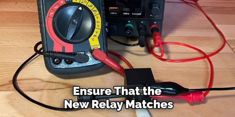
Step 10. Replace the Relay if Necessary
After completing the tests and inspections outlined in the previous steps, the final decision regarding the relay’s condition is critical. If the relay fails any electrical tests, shows noticeable physical damage, or cleaning the contacts does not restore proper function, replacement is necessary.
When selecting a replacement relay, ensure that the new relay matches the original’s specifications, including voltage and current ratings, contact configuration, and physical size to fit the socket or PCB layout. Emphasize sourcing high-quality relays from reputable manufacturers to ensure reliability and longevity. Install the new relay securely, checking it is seated correctly and connected efficiently to prevent loose connections. Finally, verify the operation of the new relay in the actual application to ascertain the successful correction of the issue, ensuring confidence in the system’s restoration and performance. This careful approach to relay replacement can help maintain the overall reliability and safety of the electrical system.
Following these steps, you can effectively troubleshoot and test a relay to determine its condition and identify potential issues.
5 Things You Should Avoid
- Using a Multimeter on a Powered Circuit: Never attempt to test a relay while it is still connected to a powered circuit. Doing so can result in inaccurate readings and potentially damage your multimeter.
- Ignoring Manufacturer Specifications: Each relay has specific specifications regarding operating voltage and current. Ignoring these can lead to inappropriate testing procedures, risking damage to the relay.
- Improper Multimeter Settings: Setting the multimeter to the incorrect mode, such as measuring resistance when you intend to check voltage, can lead to invalid results or cause harm to the device. Always double-check your multimeter settings before initiating the test.
- Not Checking for Physical Damage: Before testing, visually inspect the relay for any signs of burning, corrosion, or mechanical damage. Testing a physically damaged relay can yield misleading results and exacerbate the damage.
- Overlooking Safety Precautions: Safety should be your priority. Always wear appropriate personal protective equipment and follow standard safety protocols to prevent accidents and ensure accurate testing conditions.
Conclusion
How to test a 5 pin relay with a multimeter involves methodically verifying both the coil and the contact terminals to ensure proper functionality.
You can obtain accurate readings by following the outlined precautions and steps, including ensuring the circuit is unpowered and the relay is disconnected. Setting your multimeter to the correct mode is crucial for measuring resistance and voltage precisely. Begin by testing the relay coil for continuity to confirm its integrity. Next, test the normally open (NO) and normally closed (NC) contacts to ensure they switch correctly when the relay is energized. This thorough process helps to diagnose any issues accurately and prevents potential malfunctions in electrical systems.
Always keep safety and manufacturer guidelines in mind throughout the testing procedure for optimal results.
Occupation: Expert in Hardware Tools
Education: Bachelor’s Degree in Mechanical Engineering
Profile:
Enrique Howard is a seasoned expert in the field of hardware tools, with a robust background in mechanical engineering that underpins his extensive knowledge and skills. Holding a degree in mechanical engineering, Enrique has cultivated a deep understanding of tool design, mechanics, and the intricacies of various hardware applications. His educational foundation empowers him to innovate and refine tools that enhance efficiency and effectiveness in a wide range of industries.
Professional Focus:
Enrique’s professional focus encompasses a diverse array of areas within the hardware tools sector, including:
- Tool Design and Development: Leveraging his engineering expertise, Enrique specializes in designing tools that meet specific user needs, ensuring optimal performance and durability.
- Material Science: Understanding the properties of various materials allows him to recommend the best tools for specific applications, enhancing safety and efficiency.
- Ergonomics: He emphasizes the importance of ergonomic design in tools, striving to create solutions that reduce user fatigue and improve comfort during prolonged use.
- Sustainability: Enrique is committed to promoting environmentally friendly practices in tool manufacturing, advocating for the use of sustainable materials and processes.
- Education and Training: Through workshops, seminars, and written content, he focuses on educating both professionals and DIY enthusiasts about tool selection, maintenance, and safe usage practices.
Throughout his career, Enrique has worked on numerous projects, collaborating with manufacturers and craftsmen to develop cutting-edge hardware solutions. His expertise spans from traditional hand tools to advanced power tools, allowing him to contribute significantly to both professional and DIY communities.
As an author, Enrique shares his insights through articles, guides, and tutorials, aimed at helping enthusiasts and professionals alike navigate the complexities of hardware tools. His passion for education and practical application drives him to continually explore new technologies and methodologies, making him a trusted voice in the hardware industry.
Whether he’s writing about the latest tool advancements or providing practical tips for tool maintenance, Enrique Howard is dedicated to empowering others with the knowledge and skills necessary to excel in their hardware endeavors.